ASTM F1854 Test Methods: A Comprehensive Guide to Porous Coatings on Medical Implants

Medical implants serve an essential purpose in healthcare, providing solutions to failures or defects in human body parts. These medical implants often possess coatings that significantly enhance their functionality and compatibility with the human body. ASTM F1854 is a standard that outlines test methods for such coatings, particularly porous coatings, on medical implants.

In this article, we aim to explain what ASTM F1854 is, its importance in medical implant manufacturing, and the role of porous coatings used on these implants. We will walk through the detailed elements of these test methods, including their scope, significance, key parameters and the process of conducting these tests. Lastly, we will explore the application of these ASTM F1854 testing methods and their implications in the medical field, discussing their substantial impact on implant performance and safety.

Understanding the Basics of ASTM F1854

ASTM F1854 is a standard test method developed by ASTM International. This authoritative standard is meticulously designed to evaluate the volume percent void, coating thickness, and pore size of porous coatings on medical implants. Through precise and reliable measurement techniques, ASTM F1854 ensures that implants meet the stringent requirements set by the medical industry.

Requiring the use of specialized equipment, ASTM F1854 classifies and quantifies the physical characteristics of porous coatings, which are essential in ensuring the compatibility and functionality of medical implants within the human body. Its standardized approach facilitates consistent results across different evaluations, contributing significantly to the advancement of medical implant technology.

Importance of ASTM F1854 in Medical Implant Manufacturing

ASTM F1854 plays a pivotal role in the manufacturing of medical implants by serving as a critical quality control measure. It ensures that porous coatings adhere to specific standards essential for implants’ optimal performance and longevity. By defining the necessary properties of porous coatings through astm license agreements, ASTM F1854 guarantees that implants will function as intended once implanted into the human body.

By setting benchmarks for volume percent void and coating thickness, ASTM F1854 also contributes to the development of implants that are more compatible with human tissue, promoting quicker integration and healing. This compatibility is crucial for the success of implants over long periods.

Understanding the Role of Porous Coatings in Medical Implants

Porous coatings on medical implants serve as the bridge between the implant and human tissue. They facilitate bone ingrowth or on growth at the tissue interface, ensuring the implant’s stable integration into the body. Such coatings mimic the structure of natural bone, allowing for the seamless transfer of stress and strain from the implant to the bone without causing discomfort or rejection.

The void intercept length and the substrate interface are two critical parameters defined by the porous coating’s structure. The coating must possess an optimal void intercept length to facilitate tissue intrusion and integration, which ASTM F1854 accurately measures through stereological evaluation. The standard ensures the implant’s coating fosters a conducive environment for bone cells to attach and grow, paving the way for successful implantation.

Details of the ASTM F1854 Test Methods

Scope and Significance of ASTM F1854 Test Methods

The ASTM F1854 test methods are laser-focused on assessing the volume percent void and coating thickness plus the pore size of porous coatings – critical factors influencing an implant’s integration and function in the body. Its comprehensive scope underscores its significance in porous coating evaluation, bridging the gap between implant design and its clinical application.

This standard provides a uniform, reliable methodology that manufacturers, researchers, and regulatory bodies can depend on to ensure that porous coatings on implants meet essential biocompatibility and mechanical integrity requirements. This common ground facilitates innovation while maintaining patient safety and implant efficacy.

The Key Parameters of ASTM F1854 Test Methods

The primary focus of ASTM F1854 test methods is on three main parameters:

  • Volume Percent Void: This parameter gives crucial insights into the extent of porosity, important for tissue growth compatibility and mechanical interlock potential.
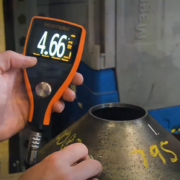
  • Coating Thickness: Accurate measurement of coating thickness ensures the durability of the porous layer and its ability to support tissue integration without degradation.
  • Pore Size: Controlling the size of the pores is essential for optimizing tissue growth into and onto the implant, directly affecting the implant’s long-term stability and functionality.

By quantifying these parameters, ASTM F1854 provides a holistic approach to evaluating the suitability of porous coatings for medical implants.

Aligning with the process of conducting ASTM F1854 test methods offers insight into how these parameters are precisely measured.

The Process of Conducting ASTM F1854 Test Methods

Conducting ASTM F1854 test methods involves several critical steps, from preparing the specimen to conducting the tests and interpreting the results. Initially, the specimen’s porous coating is carefully examined to ascertain its readiness for testing. Following this, specific methodologies like stereo logical evaluation and scanning electron microscopy are employed to ascertain the volume percent void, coating thickness, and pore size.

Throughout the testing process, adherence to the astm license agreement is vital, ensuring that all procedures are carried out according to standardized protocols. This consistency across testing ensures the reliability and reproducibility of results, fundamental for the advancement of medical implant technologies.

Application and Implications of ASTM F1854 Test Methods in the Medical Field

ASTM F1854 and Its Impact on Implant Performance and Safety

ASTM F1854 significantly impacts implant performance and safety. By setting rigorous standards for porous coatings, it ensures that implants not only fit mechanically within the human body but also encourage natural bone growth and integration. This dual success criteria – mechanical stability and biological compatibility, as outlined by ASTM F1854, directly correlate to an implant’s performance over its lifetime.

Moreover, by enabling a standardized approach to evaluating implants, ASTM F1854 plays a critical role in enhancing patient safety. Implants evaluated under these test methods can be trusted to meet high-quality standards, reducing the risk of implant failure and complications post-surgery. This level of trust and reliability is indispensable in the sensitive and life-changing field of medical implants.

ASTM F1854 Legacy Sample Preparation vs. Metrology CT Scanning Analysis

This ASTM F1854 legacy test method covers stereological test methods for characterizing the coating thickness, void content, and mean intercept length of various porous coatings adhering to nonporous substrates.

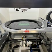
Medical Additive OEM’s showing growing interest in switching their 3D printing validation over from the legacy manual method of characterizing porosity (ASTM F1854) to using metrology grade CT 3D scanning and analysis. Correlating 2D and 3D can be done. While the standard only shows 2D techniques to simulate the 3D pores, 3D Engineering Solutions can use both in order to show a correlation and to use the new 3D methods of characterizing these structures.

The novel thing about metrology grade CT scanning these parts is that we can take many virtual slices from different areas of the sample and evaluate them. While legacy polishing

methods only allow a very limited sampling.

The FDA has used this alternative data collection method to look at, and approve at least two different medical devices to date. The advantages of metrology grade CT scanning include:

  • Shorter lead time (less than one week) vs. at least 2-3 weeks with the legacy sample preparation method (cut and polish method)
  • Non-destructive testing of sample
  • Actual medical devices can be used – test coupons are not necessary

If you’re interested in learning more about 3D Engineering’s approach, please contact us to learn more!

Non-Contact Thickness Measurements: Revolutionizing 3D Engineering Solutions


In engineering, accurate and efficient thickness measurements ensure the quality of various materials and products. Non-contact thickness measurement refers to the process of determining the thickness of a material without physically touching it. Compared to contact measurements, this cutting-edge approach avoids damage to components, eliminates the need for sample preparation, and enables faster and more efficient measurements. Non-contact thickness gauges utilize advanced technologies, including lasers, ultrasonic sensors, and optical techniques, to precisely measure the thickness of a wide range of materials, from thin films to thick substrates. The following sections will explain the basics of this measurement process and its impact on engineering solutions.

Laser Distance Sensors: High-Precision Thickness Gauges

Laser distance sensors have become increasingly popular for non-contact thickness measurements due to their exceptional accuracy and versatility. These sensors emit a focused laser beam onto the surface of the measured material. The laser light is then reflected back to the sensor, which calculates the thickness based on the time-of-flight principle or the triangulation method. Laser sensors offer high-resolution measurements, typically in the micrometers or even nanometers range, making them ideal for applications requiring precise thickness control.

Potentially add in a section talking about the details of ultrasonic thickness measurements

Applications and Benefits of Non-Contact Thickness Measurements

Non-contact thickness measurements find extensive applications across various industries, including:

  • Automotive
  • Aerospace
  • Electronics
  • Manufacturing

These measurements are essential for quality control, process optimization, and product development. By accurately measuring the thickness of materials without contact, engineers can ensure consistent product quality, detect defects or variations, and optimize manufacturing processes.

Non-contact thickness measurements have revolutionized 3D engineering, providing high-precision solutions for accurate thickness control. Laser measurement sensors, in particular, are powerful tools for measuring the thickness of materials without physical contact, offering exceptional accuracy and versatility. As the demand for precise and efficient thickness measurements grows, non-contact thickness gauges will undoubtedly play a crucial role in shaping the future of 3D engineering solutions.

Where Innovation and Expertise Converge: 3D Engineering Solutions

At 3D Engineering Solutions, we are dedicated to delivering exceptional advanced engineering metrology services with unparalleled precision and speed. Our commitment to detail is evident in every aspect of our business—from our top-notch service to our highly skilled team and the cutting-edge technology we employ.

Our advanced engineering metrology services have far-reaching applications across various industries, including aeronautics, motion picture and gaming, automotive, tool and die, manufacturing, forensics, archaeology, medicine, and maritime. Wherever precision digital 3D modeling is required, 3D Engineering Solutions will meet your needs.

At 3D Engineering Solutions, we take pride in delivering advanced engineering metrology services that exceed expectations. With our dedicated team, cutting-edge technology, and unwavering commitment to excellence, we are your trusted partner for all your precision digital 3D modeling requirements. Contact us today to get started!

Frequently Asked Questions (FAQs)

How do you measure thickness with a sensor?

Thickness can be measured with a sensor using non-contact methods such as laser triangulation or time-of-flight techniques. The sensor emits a laser beam or ultrasonic wave onto the material’s surface, and by analyzing the reflected light, it calculates the thickness based on the distance traveled by the laser or the angle of reflection. This allows for precise thickness measurements without physically touching the material.

What is the unit for thickness?

The unit for thickness is typically expressed in millimeters (mm), micrometers (μm), or nanometers (nm), depending on the scale and precision required for the specific application. Non-contact thickness gauges can measure these units, offering high-resolution data for accurate thickness control.

What is the most accurate way to measure thickness?

Non-contact thickness measurement techniques, such as those using laser sensors or ultrasonic waves, are considered the most accurate way to measure thickness. These methods provide high precision measurements without the need for physical contact, eliminating potential errors or variations caused by surface irregularities or material deformation. Laser measurement sensors or ultrasonic sensors can achieve accuracy in the range of micrometers or even nanometers, ensuring reliable and consistent thickness measurements.

What device is used to check thickness?

Non-contact thickness gauges are the devices used to check thickness without physically touching the material. These gauges employ advanced technologies like laser sensors, ultrasonic sensors, or optical methods to measure various materials’ thickness accurately. They offer high precision, fast measurement speeds, and the ability to measure a wide range of thicknesses, making them essential tools for quality control and process optimization in 3D engineering applications.

The Basics of Surface Finish Measurement

Surface finish is a measure of a material’s surface texture and characteristics. It encompasses three main components: roughness, waviness, and lay, which are crucial in determining the quality, functionality, and aesthetics of a product. Roughness refers to the finer irregularities on the surface, typically caused by the manufacturing process, such as cutting, grinding, or polishing. Waviness, on the other hand, describes the more widely spaced variations on the surface, often resulting from vibrations or deflections during manufacturing. Lay is the predominant direction of the surface pattern, which can be influenced by the manufacturing method employed. Understanding and measuring surface finish is essential for engineers and manufacturers to ensure that their products meet required specifications and perform optimally. The coming sections will delve into the basics of surface finish measurement and its importance in the engineering processes.

Why is Surface Finish Important in Engineering Processes?

Surface finish plays a vital role in various aspects of engineering, including:

  • Functionality: A component’s surface finish can significantly impact its functionality. Smooth surfaces reduce friction and wear, while rough surfaces provide better adhesion or grip.
  • Durability: A well-controlled surface finish can enhance a component’s durability by minimizing stress concentrations and improving resistance to corrosion and fatigue.
  • Aesthetics: In many applications, such as consumer products, surface finish contributes to the appearance and perceived quality of the product.
  • Assembly: The surface finish of mating components can affect their fit and alignment, influencing the performance and reliability of the assembled product.

How to Measure Surface Finish

Surface finish measurement involves quantifying the surface texture of a material. There are several methods and tools available for measuring surface finish, including:

  • Stylus Profilometers: These instruments use a stylus that physically contacts the surface and traces its profile. The stylus moves across the surface, and its vertical displacement is recorded to generate a 2D surface texture profile.
  • Optical Profilometers: Non-contact optical methods, such as white light interferometry or confocal microscopy, use light to measure surface topography. These techniques provide high-resolution 3D surface maps without physically contacting the surface.
  • Comparison Plates: Surface finish comparison plates, also known as surface roughness standards, provide a visual reference for comparing the surface finish of a component against a known standard. These plates feature a range of surface finishes that can be visual or tactile compared to the sample surface.

Understanding Surface Roughness Charts

Surface roughness charts are visual representations of different surface finishes, typically arranged in order of increasing roughness. These charts help engineers and technicians quickly identify and specify the desired surface finish for a particular application. Common surface roughness parameters include Ra (average roughness), Rz (average maximum height of the profile), and Rq (root mean square roughness). Each parameter provides a different perspective on the surface texture and is selected based on the application’s specific requirements.

Surface finish measurement is a critical aspect of engineering that ensures the quality, functionality, and aesthetics of manufactured components. Engineers can make informed decisions in design and manufacturing processes by understanding the basics of surface finish, including its components, importance, and measurement techniques. Whether using stylus profilometers, optical methods, or comparison plates, accurate surface finish measurement is essential for producing high-quality products that meet the demands of various industries.

Precision, Passion, and Partnership: 3D Engineering Solutions

At 3D Engineering Solutions, we are dedicated to delivering exceptional service, employing the best engineers, and utilizing cutting-edge technology to provide advanced engineering metrology solutions. Our commitment to detail is unwavering, and we strive to exceed client expectations in every aspect of our work.

We pride ourselves on providing fast, efficient, and cost-effective solutions. Our state-of-the-art digitization technologies and high-end point cloud engineering software enable us to capture and process up to 1,000,000 points per second, ensuring quick turnaround times without compromising on quality or precision. Our services have applications across various industries, including aeronautics, motion picture and gaming, automotive, tool and die, manufacturing, forensics, archaeology, medicine, and maritime – wherever precise digital 3D modeling is required.

Your success is our top priority, and we are committed to utilizing superior communication, attention to detail, high-quality standards, and innovative technologies to fulfill your quality and engineering needs. Choose 3D Engineering Solutions for advanced engineering metrology services that consistently deliver excellence.

Frequently Asked Questions (FAQs)

What unit of measure is surface finish?

Surface finish is typically measured in nanometers (nm) or microinches (μin). These units represent the surface’s average roughness (Ra), which is calculated by measuring the vertical deviations of the surface from its mean line.

How do you check the surface finish of metal?

To check the surface finish of metal, you can use various methods, such as visual inspection, tactile comparison against surface roughness standards, or employing surface measurement instruments like stylus profilometers or optical profilometers. These tools provide quantitative measurements of the surface roughness parameters, enabling accurate assessment of the surface finish.

What is a surface finish measurement tool?

A surface finish measurement tool is an instrument used to quantify the surface texture of a material. Common tools include stylus profilometers, which use a tiny precision stylus to trace the surface profile, and optical profilometers, which utilize non-contact methods like white light interferometry or confocal microscopy to measure surface topography. These tools provide detailed information about surface roughness parameters, aiding in quality control and process optimization.

Non-Contact Distance Measurements: Accurate Measurement Solutions

In metrology and industrial automation, non-contact distance measurements have revolutionized the way we measure objects and distances. Non-contact distance measuring devices determine the distance to an object without making physical contact. These devices rely on various technologies, such as lasers, structured light, and X-rays, to reliably and precisely measure objects without physical contact with the target object. The coming sections explore the fascinating realm of non-contact distance measurement devices, their types, and their advantages over contact-based sensors.

Types of Non-Contact Sensors

Several types of non-contact sensors are commonly used for distance measurements. These include:

  • Laser Distance Sensors: Non-contact laser sensors utilize laser technology to measure distances accurately. They emit a focused laser beam that reflects off the target object, and the time (or, in some cases, frequency) taken for the beam to return is used to calculate the distance. Laser distance sensors offer fast response times, long measurement ranges, and the ability to measure small objects or intricate surfaces.
  • Structured Light Sensors: Structured light sensors, such as those based on triangulation, use light to measure distance. Triangulation sensors project a beam of light onto the target object and capture the reflected light using a camera or detector. By analyzing the position of the reflected light, the sensor calculates the distance.
  • X-Ray Sensors: X-ray systems through computed tomography, or CT scanning, take thousands of X-rays and reconstruct them into a 3D volume called a voxel data set (voxel stands for volume metric pixel).

Non-Contact Laser Measurement and Sensors

Non-contact laser measurements and sensors have gained popularity due to their accuracy, speed, and versatility. Laser-based systems offer several advantages:

  • High Precision: Laser sensors can achieve micron accuracy, making them ideal for applications that require precise measurements, such as quality inspection and surface profiling.
  • Long Range: Laser sensors have an entire measuring range from a few inches to hundreds of feet, without compromising accuracy. This capability is valuable in large-scale industrial settings or outdoor applications.
  • Fast Response: Laser sensors provide near-instantaneous measurements, enabling real-time monitoring and control of processes. This responsiveness is necessary in high-speed manufacturing and automation systems.
  • Non-Contact Operation: Laser sensors minimize the risk of damage or contamination by eliminating physical contact with the target object, which is valuable when measuring delicate or sensitive materials.

Non-contact distance measurements have transformed the landscape of metrology and industrial automation. With their accuracy, speed, and versatility, non-contact sensors provide reliable solutions for various applications. Whether using laser, structured light, or X-ray technologies, these advanced devices offer the benefits of non-intrusive measurement, long-range capabilities, and fast response times. As industries evolve, non-contact distance measurements will drive innovation and efficiency across various sectors.

Measuring Excellence at 3D Engineering Solutions

At 3D Engineering Solutions, we pride ourselves on our ability to handle complex projects with ease. Our engineers have a wealth of experience in various industries, including aerospace, automotive, manufacturing, and more. We leverage this expertise to tackle challenging measurement tasks, delivering results that exceed expectations.

As a company, we are committed to innovation and continuous improvement. We stay up-to-date with the latest non-contact distance measurement technology advancements, giving our clients access to the most advanced solutions. Our goal is to be your trusted partner, providing reliable and efficient measurement services that drive your success.

When you choose 3D Engineering Solutions, you can expect unmatched service. We are dedicated to building long-term relationships with our clients that go above and beyond the highest standards of quality and accuracy.

If you’re looking for a partner who combines technical expertise with a customer-centric approach, look no further than 3D Engineering Solutions. Contact us today to learn how we can help you achieve your goals.

FAQs

What are non-contact distance measuring devices?

Non-contact distance measuring devices are instruments that determine the distance to an object without making physical contact. They use lasers, structured light sensors, or X-rays to measure distance.

What are the types of non-contact sensors?

The common types of non-contact sensors include laser sensors, structured light sensors, and X-rays. Laser sensors use laser beams, structured light sensors project pattern of light, and X-rays see through parts.

What is the difference between contact and non-contact sensors?

Contact sensors require physical contact with the target object, while non-contact sensors measure distances without direct contact. Non-contact sensors offer non-intrusive measurement, reduced risk of damage, and the ability to measure delicate or inaccessible objects.

ISO 17025 vs ISO 9001: Understanding the Key Similarities and Differences

Two of the most well-known standards for quality management systems (QMS) are ISO 17025 and ISO 9001. Both aim to manage quality objectives and improvement, but have distinct scopes and applications. ISO 17025 specifies the general requirements for the competence, impartiality, and consistent operation of testing and calibration laboratories and is designed to monitor precise and reliable results. ISO 9001, on the other hand, is an international standard designed for customer satisfaction that can be applied to any organization, regardless of size, type, or industry. The following sections will delve deeper into the similarities and differences between ISO 17025 and ISO 9001, helping you understand which standard is best suited for your organization.

Key Similarities Between ISO 17025 and ISO 9001

While ISO 17025 and ISO 9001 have distinct scopes and applications, they share key similarities contributing to their effectiveness. The application of both standards concentrates on customer satisfaction. Here’s a more thorough explanation:

  • Continuous Improvement: Both standards emphasize the importance of continually improving processes, products, and services to meet customer needs.
  • Customer Focus: ISO 17025 and ISO 9001 prioritize meeting customer requirements to improve satisfaction.
  • Management Responsibility: Both standards require top supervision to demonstrate leadership and commitment to the quality management system.
  • Document and Record Control: Effective document and record management are traits of both ISO 17025 and ISO 9001 to guarantee the integrity and traceability of information.

Key Differences Between ISO 17025 and ISO 9001

Despite sharing some common elements, ISO 17025 and ISO 9001 have significant differences setting them apart. These differences arise from their scopes, technical requirements, and areas of emphasis:

  • Scope: ISO 17025 focuses specifically on the competence of testing and calibration laboratories, while ISO 9001 covers an organization’s entire quality management system.
  • Technical Requirements: ISO 17025 includes detailed technical requirements for testing and calibration methods, equipment, and personnel competence, which are not covered in ISO 9001.
  • Impartiality and Confidentiality: ISO 17025 strongly emphasizes impartiality and confidentiality in laboratory operations, which are not explicitly addressed in ISO 9001.

ISO 9001 or ISO 17025: How to Choose a Calibration Company

When selecting a calibration company, consider its qualifications and the standards it adheres to. Your industry or customers require specific technical competence and reliable calibration results, so choosing an ISO 17025 accredited calibration laboratory is vital.

Accreditation vs. Compliance: What’s the Difference?

Accreditation and compliance are frequently used terms when discussing ISO standards, but they have different meanings and implications. While both involve an assessment of an organization’s competence or conformity to management system requirements, they focus on different aspects. Accreditation is a formal recognition of a laboratory’s competence by an outside entity to perform specific tests or calibrations according to ISO 17025, while compliance is a self-assessment of an organization’s adherence to the requirements of ISO 17025.

  • Accreditation: Formal recognition by an accreditation body that a laboratory is competent to perform specific tests or calibrations per ISO 17025 requirements.
  • Compliance: Internal promise to follow the guidelines of ISO 17025.

Maximizing the Benefits of ISO 17025 and ISO 9001

Implementing both ISO 17025 and ISO 9001 can provide organizations with powerful benefits that enhance their performance and competitiveness. These standards are complementary when implemented simultaneously, helping organizations to:

  • Enhance quality management while managing the competence and reliability of testing and calibration results.
  • Improve customer satisfaction by consistently meeting requirements and delivering accurate results.
  • Gain a competitive advantage by demonstrating a commitment to quality objectives and technical competence.
  • Facilitate continual improvement across the entire organization, including laboratory operations.

Understanding the similarities and differences between ISO 17025 and ISO 9001 is helpful for organizations seeking to improve their quality management systems and laboratory operations. While ISO 17025 focuses on the competence and reliability of testing and calibration laboratories, ISO 9001 covers the entire quality management system of an organization. By integrating both standards, organizations can maximize their benefits, enhance customer satisfaction, and gain a competitive edge in their respective markets.

3D Engineering Solutions: Where Precision Meets Passion

At 3D Engineering Solutions, we are passionate about precision and committed to delivering exceptional service to our clients. As a leading provider of advanced engineering metrology services, we understand the importance of accuracy and efficiency in every project we undertake.

Our commitment to quality is unwavering, and we partner with only the best in the industry to guarantee that we have access to the most advanced tools and technologies available. From high-speed, touchless scanning to unsurpassed accuracy in data capture, our technology partners set the standard for excellence in engineering metrology.

At 3D Engineering Solutions, we understand that every project is unique, and we approach each with the same dedication and attention to detail. We aim to provide effective solutions that meet your needs and help you succeed. Whether in the automotive industry, aerospace, manufacturing, or any other field that requires precision digital 3D modeling, we have the expertise and technology to deliver results you can count on. Contact us today to learn more about our solutions.

See why we were named the 2024 Quality Engineering Plant of the Year 

FAQs

What is ISO 17025 equivalent to?

ISO 17025 is the main ISO standard used by testing and calibration laboratories. It is the laboratory equivalent of ISO 9001 for manufacturing and service organizations. ISO 17025 focuses on laboratory competence, impartiality, and consistent operation.

What does it mean to be ISO 17025 certified?

Being ISO 17025 certified means that a laboratory has been independently assessed and found to be competent in performing specific tests or calibrations. Accreditation to ISO 17025 demonstrates a laboratory’s technical competence and ability to produce precise, accurate results.

What are the three types of audits in ISO 9001?

The three types of audits in ISO 9001 are internal audits, customer audits, and certification audits. Internal audits are first-party audits conducted by the organization itself to assess its own management system. Customer audits are second-part assessments conducted by customers or on behalf of customers to verify the organization’s compliance, and certification audits are third-party evaluations conducted by independent certification bodies to assess compliance with ISO 9001 requirements.

What is the advantage of ISO 17025?

ISO 17025’s main advantage is that it provides a globally recognized framework for establishing and demonstrating the competence, impartiality, and consistent operation of testing and calibration labs. Accreditation to ISO 17025 helps laboratories ensure the accuracy and reliability of their results, enhancing customer confidence and trust.

Celebrating 3D Engineering Solutions: Quality’s 2024 Plant of the Year

3D Engineering Solutions is honored to be named Quality Magazine’s 2024 Plant of the Year! Check out the article here

Our goal as a company is to stand out as a beacon of innovation with a relentless dedication to quality, and a people-first approach. We cross-train engineers on every piece of our equipment and pride ourselves on offering a great work environment, addressing any complications without blame. Above all, quality is what guides all of our work. Our quality work has led to thousands of happy customers, and we don’t leave work until it’s correct.

The recognition of 3D Engineering Solutions as Quality’s 2024 Plant of the Year marks a significant achievement, not only for our company but also for the broader engineering and manufacturing sectors. This accolade underscores the pivotal role played by advanced 3D engineering technologies in enhancing manufacturing standards, quality control protocols, and product development processes on a global scale. 

Through cutting-edge techniques such as long-range laser scanning, industrial CT scanning, and additive manufacturing, we hope to exemplify the transformative potential of these technologies within contemporary manufacturing practices.

Why 3D Engineering Solutions?

We believe that this prestigious accolade from Quality Magazine, a leading publication in the field, is a testament to our high standards and dedication to quality, and we are grateful for the recognition!

If you’re looking for 3D scanning work, our Cincinnati-based company would love to take on your project! We offer various services, including:

  • Reverse engineering
  • Quality control
  • Fixture and tool design
  • ISO 17025 certified inspection services
  • 3D digitizing
  • Noncontact laser scanning

Contact 3D Engineering Solutions Today!

What Is X-Ray Machine PCB Inspection?

What Is X-Ray Machine PCB Inspection? With so many electronics on the market today, reliable functionality is what separates quality products from the competition. Everyday consumers count on their gadgets to work when they need them to. But for professionals in medicine, aerospace, and military operations, properly functioning electronics can quite literally be a matter […]

What Is Metrology and Why Is It Needed?

What is Metrology and Why is it Needed?

Metrology is the scientific study of measurement. This field of study defines measurements under a common understanding, applies these measurements in practice, and uses them in analysis across industries. Because of its broad applicability, metrology is used worldwide to establish accuracy and precision in many critical fields.

Continue Reading

, ,

What Is a CMM Machine: Components, Uses, and Benefits

What Is a CMM Machine? Components, Uses, and Benefits of CMM Measurement

Strong manufacturing depends on the precise measurement of parts and components. Every part needs to be identical to ensure correct functionality, but sometimes, irregularities in fabrication and production can lead to discrepancies in the dimensions of manufactured parts. Without accurate measurement, dimensional errors can result in products failing to operate properly.

Continue Reading

Steps in the Reverse Engineering Process

How Does Reverse Engineering Work?

Reverse engineering is the process of analyzing and deconstructing something to see how it works. An example would be taking apart an alarm clock to understand what each piece does – and how the pieces work together.

Continue Reading

, ,